Scalextric RMS Interface Cable
This page describes how to make a Scalextric RMS sensor compliant with Ultimate Racer, by simply wiring up a cable.
Many thanks to Dr Vanski for this great job and simple, efficient design.
Dr. Vanski's easy Scalextric RMS Interface Cable
Parts List
- 1 x Scalextric C8147 RMS Multi-Lane extension
- 1 x DB25 male parallel connector
- 1 x 1/8" stereo headphone female mini-jack
- 1 x 20' stereo walkman headphone extension cable
- 3 x short pieces of coloured wire (red, green, and black)
- 6 x short pieces of narrow heat shrink tubing
- 2 x short pieces of larger heat shrink tubing
I got the wire, heat shrink tubing, and connectors at my local Radio Shack. Your local Scalextric dealer can get you the C8147, or order it online from any reputable mail order slot car store.
Instructions:
Connect & Check Parallel Port
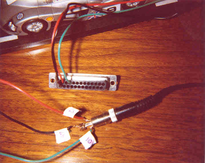
Connect the wires to pins 25 (black), 12 (red), and 10 (green) of the DB25 connector. Apply a drop of solder even with crimped connectors to make sure you have a nice solid connection.
Connect the DB25 plug to your parallel port and check that UR "sees" the connections. I have set lane 1 to detect as pin 10 and lane 2 to detect as pin 12. The green dots in the Setup screen should turn grey when the wire from pin 25 touches either the wire from pin 10 or 12. If this all works then unplug the DB25 connector from your computer, heat shrink the end of each wire, and then put the bigger heat shrink tubing around all 3 wires to hold them together nicely.
Connect & check Mini Jack
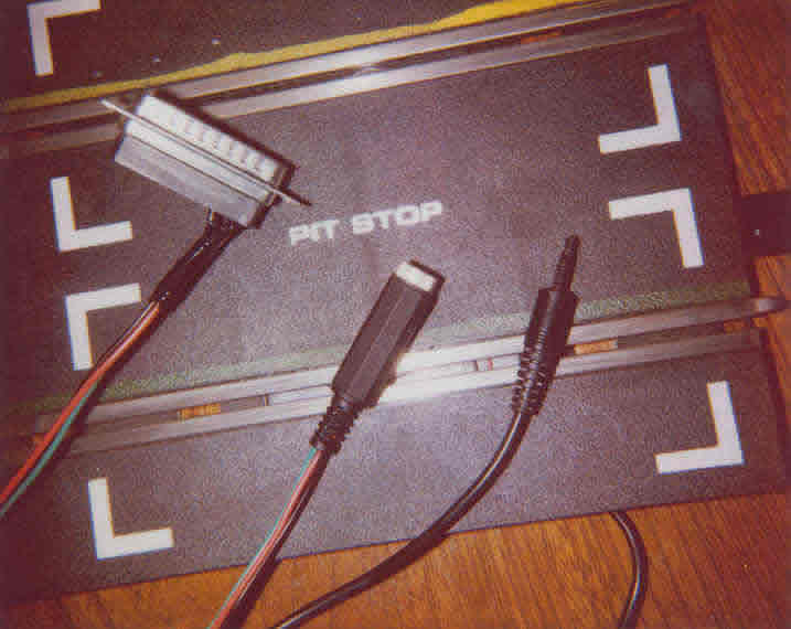
Slide the insulating shield for the stereo headphone mini-jack over all three wires. Slide one piece of larger heat shrink tubing over all three wires. Slide one piece of smaller heat shrink tubing over each individual wire. Connect the red wire to the copper connector on the mini-jack, the green wire to the silver connector, and the black wire to the long piece coming out of the mini-jack. Apply a drop of solder to make sure you have a good connection.
Push the stereo mini-plug from C8147 into the mini-jack. Connect the DB25 to your computer. Slide a slot car over the switch in the C8147 and again check that the green dots turning grey in the Setup screen of UR.
Once you are sure this works for each lane, unplug the C8147 and DB25 connectors and heat shrink each individual wire. Then heat shrink all three wires together on the mini-jack. Screw the insulating cover back onto the mini-jack.
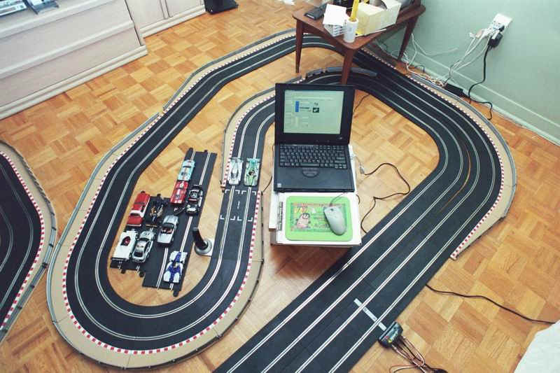
Install the C8147 into your track. Connect it to the headphone extension cable. Run the extension cable over to your computer and plug it into the mini-jack. Plug the DB25 connector into your computer, fire up Ultimate Racer, and RACE!
Place the C8147 on a slow part of your circuit, or in a braking zone. This will ensure that the car's guide is planted firmly in the slot as it crosses this section of track. In this case, the C8147 is located just in front of the 2 cars on the track.