
Hardware : Lane Supply Controller with timer
This page describes a lane power supply switch. It allows you to switch the lane power on or off from the computer.
The lane supply controller circuit allows you to control each lane power supply from the PC using the parallel port.This system is used to switch on/off power supply on lanes during a staggered race or to switch off power supply after a bad start.
These designs are free of charge for personal use only.
All schematics have been built with Eagle. Eagle project files are available thru a mail request.
Contact support@uracerweb.org for any commercial use of the designs.
Lane supply controller
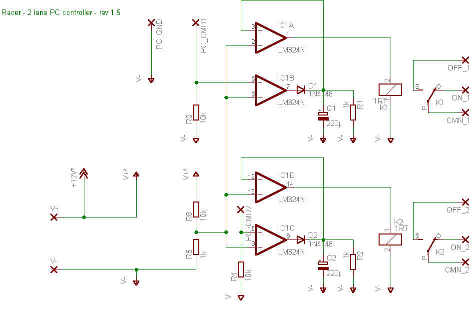
Schematic :
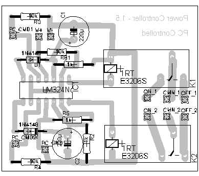
Placement
PCB
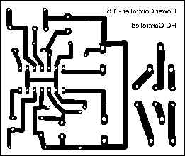
Real PCB size : 65mm x 55mm
Part list :
- IC1 : LM324 -x4 ampli op
- C1, C2 : capacitor 220µF
- K1, K2 : 1RT standard relay - 12V/5A
- D1, D2 : diods 1N4148
- R1, R2, R5 : resistor 1k - 0.25W
- 1x Parallel port connector
- R3, R4, R6 : resistor 10k - 0.25W
- ribbon cable + standard cable
External connections :
| PC_CMD1 | connected to one PC parallel port interface output pin (pins 2 to 9). Controls relay K1 |
| PC_CMD2 | connected to one PC parallel port interface output pin (pins 2 to 9). Controls relay K2 |
| PC_GND | connected to one PC ground pin (pins 18 to 25) |
| PWR_V+ | connected to external power supply (+) output. Power supply voltage : 12V |
| PWR_V- | connected to external power supply (-) output. |
| CMN_1, CMN_2 | relay : common lane power supply |
| ON_1, ON_2 | relay : on contact |
| OFF_1, OFF_2 | relay : of contact |
Detailed description :
The lane relay is by default connected on the 'on contact status relay' in order to be able to play even when the computer is down (!!!).
The computer system should put the parallel port interface pin on 'off status' to switch off power supply on the lane the switch is connected. Example for relay K1 (same for relay K2) :

If you play with Ultimate Racer the pin number you solder the PC_CMD output should be specified in the hardware parameters. Ex : if a controller is soldered on pin 5 on LPT1, specify it as follow :
| Enabled | Event | Param1 | Param2 |
| Actif | LPT - Control power supply | LPT1 | 5 |