
Tutorial
Planning a 3 lane routed track. Part 1
Overview
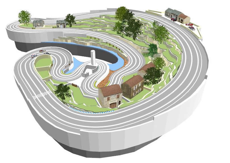
Myself and a couple of friends are planning to build a three lane routed wooden track with full scenery and elevations
This tutorial will outline the planning process and will involve...
- Planning the track
- Varying lane widths to add squeezed sections
- Using track elevations
- 3d models
- 3d landscape
Let's get Started
To open the Layout Editor -
 Click on the Layout Editor button in the Left-bar or on the Home Page
 Or choose "Edit a track layout " from the Views list in the Header Menu
 - Or press F9 on your keyboard F9
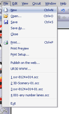
Create a new layout
Choose your track brand
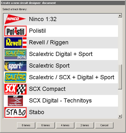
In this case we'll choose SXR 1/24 as our starting point, but we'll actually be switching between libraries to produce our layout. The SXR track libraries are specifically designed for designing scratchbuilt, routed wooden tracks.
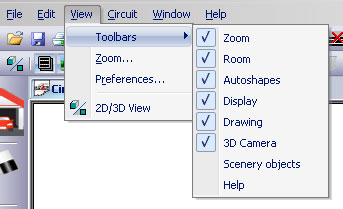
Choose Toolbars
In the View menu I'll switch on the Zoom, Room, Autoshapes, Display, Drawing and 3D Camera toolbars
Room Plan
Normally we'd start by laying out the room in which the track will be situated, to get an idea of the space available. In this case however, the track will be situated in the corner of a large warehouse, so space will not be an issue.
So I think we'll skip this stage and move straight on to planning our track layout.
Track Basics
Our track will start from an idea, or theme. We'd like to base our track around a small Mediterranean village, with a coastal inlet at the front, and hills rising up to the back. We'd like a very tight and twisting section along the coastal route at the front, and then some wide, swooping, high speed, sections rising into the hills at the back.
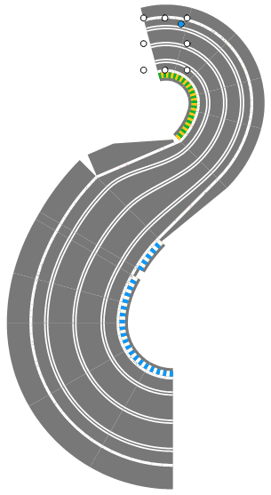
So we'll start with the seafront section past the village which is flat. We'll put a single corner section into the layout.
Using the 3 lane curve tab, we click on the section called 3-10-C20-30, which signifies that this section has 3 lanes, with a lane width of 10cm, it's a corner with an inner radius of 20cm and an angle of 30°. We don't really need to remember all of that, but it's useful to understand the naming structure of the SXR track libraries as it gives you an understanding of the sizes of the track sections you are using.
Now we'll elevate this track section to the height we require
![]() We'll switch on the Show elevations tool. This will show track elevations in a blue circle. At the moment though, there are no track elevations, so there is nothing to show
We'll switch on the Show elevations tool. This will show track elevations in a blue circle. At the moment though, there are no track elevations, so there is nothing to show
![]() Then we'll click on the Raise tool which allows us to elevate either track or objects. When the Raise tool is selected a single click on any track section raises it by a single unit (2.5cm), a Ctrl click raises by 5 units (12.5cm) and a Shift click raises by 10 units (25cm).
Then we'll click on the Raise tool which allows us to elevate either track or objects. When the Raise tool is selected a single click on any track section raises it by a single unit (2.5cm), a Ctrl click raises by 5 units (12.5cm) and a Shift click raises by 10 units (25cm).
![]() As you might expect, the Lower tool works in the same way, but decreases elevations
As you might expect, the Lower tool works in the same way, but decreases elevations
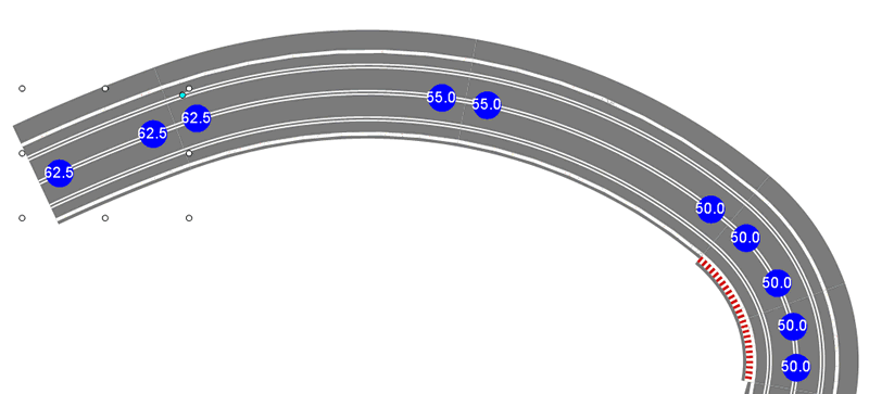
So by using the Raise tool I'll raise the track section to a height of 50cm.
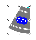
You can now see two blue circles showing the elevation at both ends of the track, in this case both are 50cm.
If you prefer to use inches rather than centimetres you can change the settings by going to View > Preferences > Grid and rotation settings and changing the Major Grid units to "in" or "ft"
Now that we've set the height of the track section, I can add in some more track pieces.
![]()
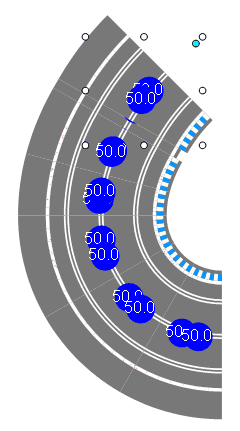
![]() I'm going to add inner and outer borders as I go along for this design. In most cases it's easier to leave borders until the layout is a bit more established, but here, we're about to swap over to a different track library, so the borders for this library and these track sections will no longer be available.
I'm going to add inner and outer borders as I go along for this design. In most cases it's easier to leave borders until the layout is a bit more established, but here, we're about to swap over to a different track library, so the borders for this library and these track sections will no longer be available.
Using more than one track library
![]() For the next part we'll switch off the Show elevations tool.
For the next part we'll switch off the Show elevations tool.
Now, at this point I want to squeeze the track, which means I want to narrow the distance between the slots, known as the lane width.
There are special track sections in the SXR libraries to do this, under the Misc (miscellaneous) tab.
These special track sections act like converters, which can join together two different libraries in the SXR collection. In this case the track section takes us from 10cm lane width, which corresponds to the 1/24 library, down to 6cm lane width which corresponds to the 1/43 library. It's called 3-10~6-S30
So now, to continue our track we need to swap over to the SXR 1/43 library. To do this we can either go to Circuit > Track Library or we can click on the library logo in the Frequently used tab of the Library toolbar
Now we can add more track.
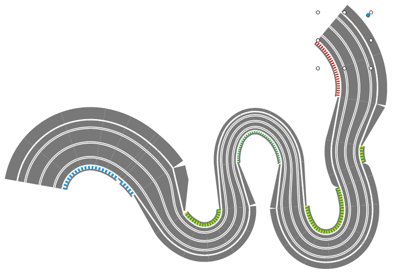
Next we'll squeeze the track even more, then we'll start to open it out again. Here we've also rotated the track, just to fit on the screen better.
Track elevations
Now we'll start the uphill section.
![]() We'll switch the Show elevations tool back on again.
We'll switch the Show elevations tool back on again.
Then we'll add two long sweeping curves.
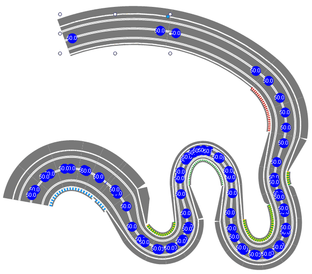
Here you can clearly see the two blue circles at each end of the track sections.
![]()
![]() When you've selected the Raise tool or the Lower tool, you can then click on a track section to change it's elevation.
When you've selected the Raise tool or the Lower tool, you can then click on a track section to change it's elevation.
The method I prefer to make hills and inclines might sound a bit complicated, but here goes anyway.
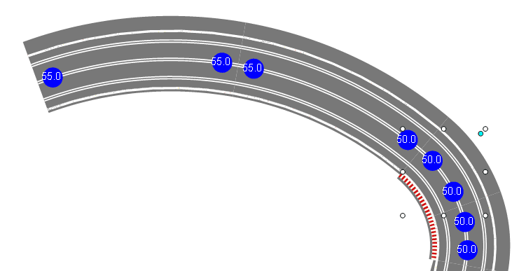
On the second of the two curves I added above, the one to the left, I click on the track section with the Raise tool selected (actually I've clicked twice). This raises that piece of track by 5cm, but leaves it flat (now 55cm at both ends), but the piece to the right is now inclined (50cm at one end, 55cm at the other).
Then I continue in the same way. Add another track section and raise it. Again the previous track section is now inclined. Add another track section and raise it, and so on.
Making a good hill can be tricky, but here are a few tips.
- Keep checking the 3D view to see how the elevations look
- Set the 3d Camera to a low view point so the elevations are clearer
- Longer sections of track will require a greater elevation rise than shorter sections to achieve a similar angle of inclination.
- Hills usually level out at the top and bottom, and reach their steepest angle in the middle. This also makes them easier to build.
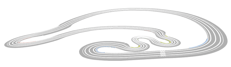
So after much experimentation with inclines, elevations and track design, we finally have a track layout we're happy with.
In the next stage we'll start to build our landscape, scenery and table